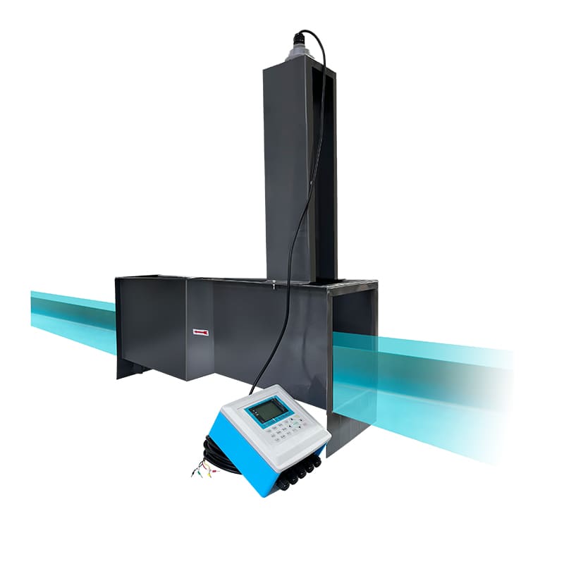
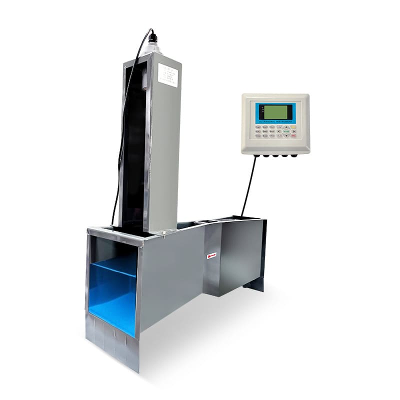
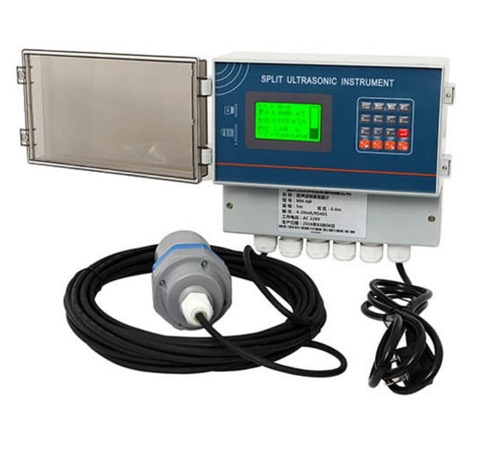
Ultrasonic Open-Channel Flowmeter
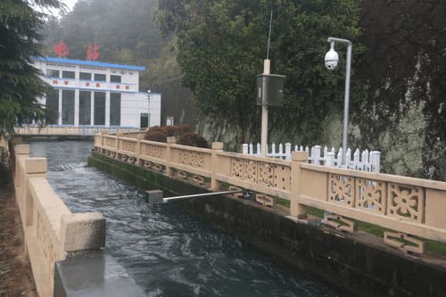
Non-contact flow measurement in open channels using dual ultrasonic sensors—velocity sensor mounted on channel wall above waterline combined with level sensor to calculate flow via velocity-area method. Zero in-channel installation eliminates sensor fouling, debris damage, and confined space entry while delivering ±3% to ±5% accuracy for municipal stormwater monitoring, irrigation canals, and wastewater applications.
- Channel Size: 100mm – 10,000mm (width or diameter)
- Flow Accuracy: ±3% to ±5% of reading
- Velocity Range: 0.03 – 15 m/s
- Level Range: 50mm – 10,000mm
- Installation: Non-contact (no in-channel sensors)
- Power: 220V AC or 12V DC / Solar + Battery
Request a QuoteTechnical Consultation
Non-Contact Measurement Without In-Channel Installation
- Zero in-channel installation—no confined space entry required
- 90% faster maintenance—service from walkway without channel entry
- All-weather operation—measures through ice and debris
- 30-40% lower total cost vs. electromagnetic systems
Parameter | Specification |
|---|---|
Measurement Principle | Velocity-area method: ultrasonic velocity × ultrasonic level |
Velocity Technology | Doppler ultrasonic (measures velocity from suspended particles/bubbles) |
Application | Open channels, canals, partially filled pipes, ditches, streams |
Channel Size Range | 100mm – 10,000mm (width or diameter) |
Channel Shape | Rectangular, trapezoidal, circular, U-shape, custom profiles |
Flow Accuracy | ±3% to ±5% of reading (application and conditions dependent) |
Velocity Accuracy | ±2% of reading (with adequate particle density) |
Level Accuracy | ±3mm or ±0.3% (whichever is greater) |
Velocity Range | 0.03 – 15 m/s (bidirectional measurement) |
Level Measurement Range | 50mm – 10,000mm (sensor-dependent) |
Minimum Flow Depth | 50mm (below velocity sensor) |
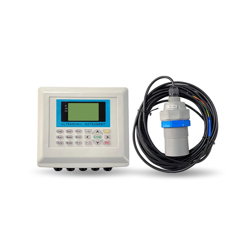
Velocity Sensor | Ultrasonic Doppler, non-contact, wall-mounted or overhead |
Level Sensor | Ultrasonic non-contact, mounted above maximum water level |
Beam Angle | Velocity: 8-15°, Level: 6-10° |
Power Supply | 220V AC (standard) | 12V DC | Solar panel + battery (off-grid) |
Output Signals | 4-20mA, RS485 Modbus, Pulse, Relay (alarm) |
Communication | Modbus RTU, GPRS/4G wireless (optional), NB-IoT (optional) |
Data Logging | 20,000+ records internal memory, SD card expansion |
Display | LCD: instantaneous flow, level, velocity, accumulated volume, signal quality |
Protection Rating | Velocity sensor: IP67 | Level sensor: IP67 | Converter: IP65 |
Quality Standards | CE Certification |
Ultrasonic Flow Monitoring Across Open Channel Applications
Non-contact measurement for stormwater, irrigation, wastewater, and environmental monitoring
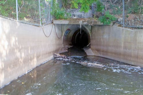
Urban Stormwater & CSO Monitoring
- Stormwater outfall measurement
- Combined sewer overflow tracking
- Detention basin discharge
- Storm drain flow monitoring
- Urban runoff quantification
- Real-time flood warning systems
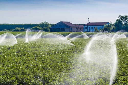
Irrigation Districts & Water Delivery
- Main canal flow measurement
- Lateral delivery to farms
- Water rights verification
- System efficiency monitoring
- Automated gate control integration
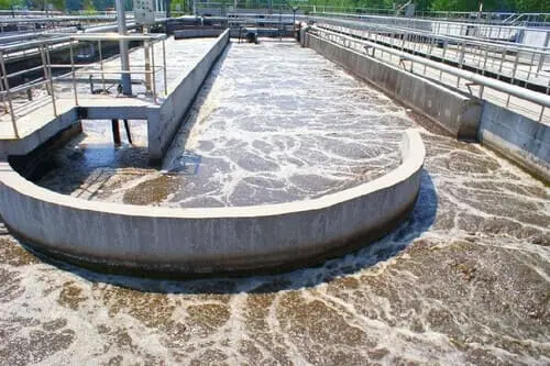
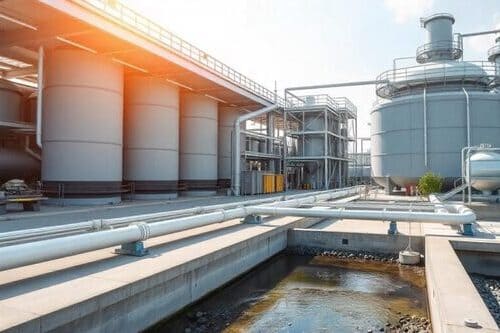
Wastewater Treatment Plants
- Plant influent flow (with debris)
- Primary effluent monitoring
- Secondary clarifier overflow
- Final effluent discharge
- Storm flow peak tracking
- Bypass flow detection
Natural Stream & River Monitoring
- Stream gauging stations
- River flow measurement
- Flood forecasting networks
- Watershed hydrology studies
- Environmental flow assessment
- Fish migration monitoring
Industrial & Mining Discharge
- Process water discharge
- Mine dewatering channels
- Industrial effluent monitoring
- Cooling water return flows
- Quarry water management
- Construction site drainage
Proper installation ensures long service life and measurement accuracy
Critical Installation Requirements
1. Pipe Orientation
Install on horizontal or vertical upward-flowing pipe sections to prevent solids settlement. For horizontal pipes, position electrodes on horizontal centerline (3 and 9 o’clock) to avoid electrode coating by settled solids.
2. Straight Pipe Requirements
- Upstream: 5D minimum (10D preferred for heavy slurries)
- Downstream: 2D minimum
- Where D = pipe diameter
3. Flow Direction
Arrow on sensor body must align with slurry flow direction. Reversed flow will cause negative readings and potential electrode damage.
4. Grounding
Essential for accurate measurement. Use grounding rings for non-conductive pipes. Ensure electrical continuity between slurry and sensor electronics.
5. Location Selection
- Avoid pump suction side (risk of negative pressure)
- Install on pump discharge side where slurry is fully mixed
- Avoid high points where gas can accumulate
- Accessible location for maintenance and electrode inspection
Pipe Material Considerations
- Steel or Lined Steel Pipes: Direct flange mounting. Verify coating inside pipe does not create grounding path issues.
- Rubber-Lined or Polymer-Lined Pipes: Use grounding rings or electrodes. Consult factory for proper grounding configuration.
- Slurry-Specific Requirements: For coal slurry, install with slight upward slope (2-5°) to prevent settlement. For high-concentration mineral slurries, consider full-bore ball valves for isolation (gate valves trap solids)
Request Your Quote Now
Specify your channel type and dimensions today—receive system recommendations within 24 hours.
info@hbmeter.cc
(+86) 152-3780-0315
1 Jingsan North Road, Xiangfu District, Kaifeng, Henan 475004 China
About HBmeter
HBYB is a specialized flow instrumentation brand combining engineering depth, continuous product innovation, and practical industry experience to deliver reliable flow measurement solutions for demanding industrial applications.