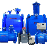

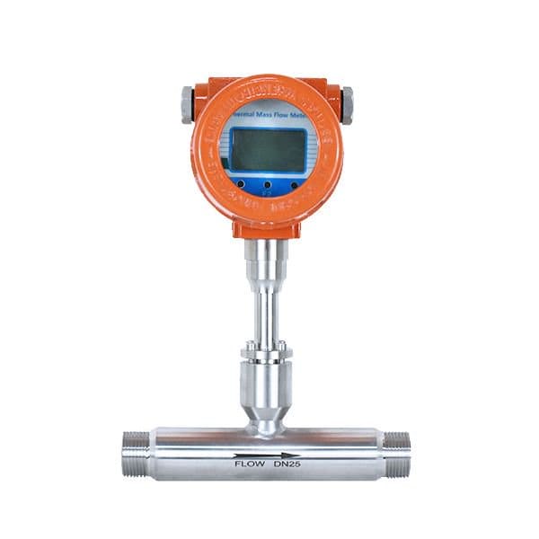
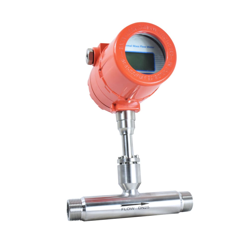
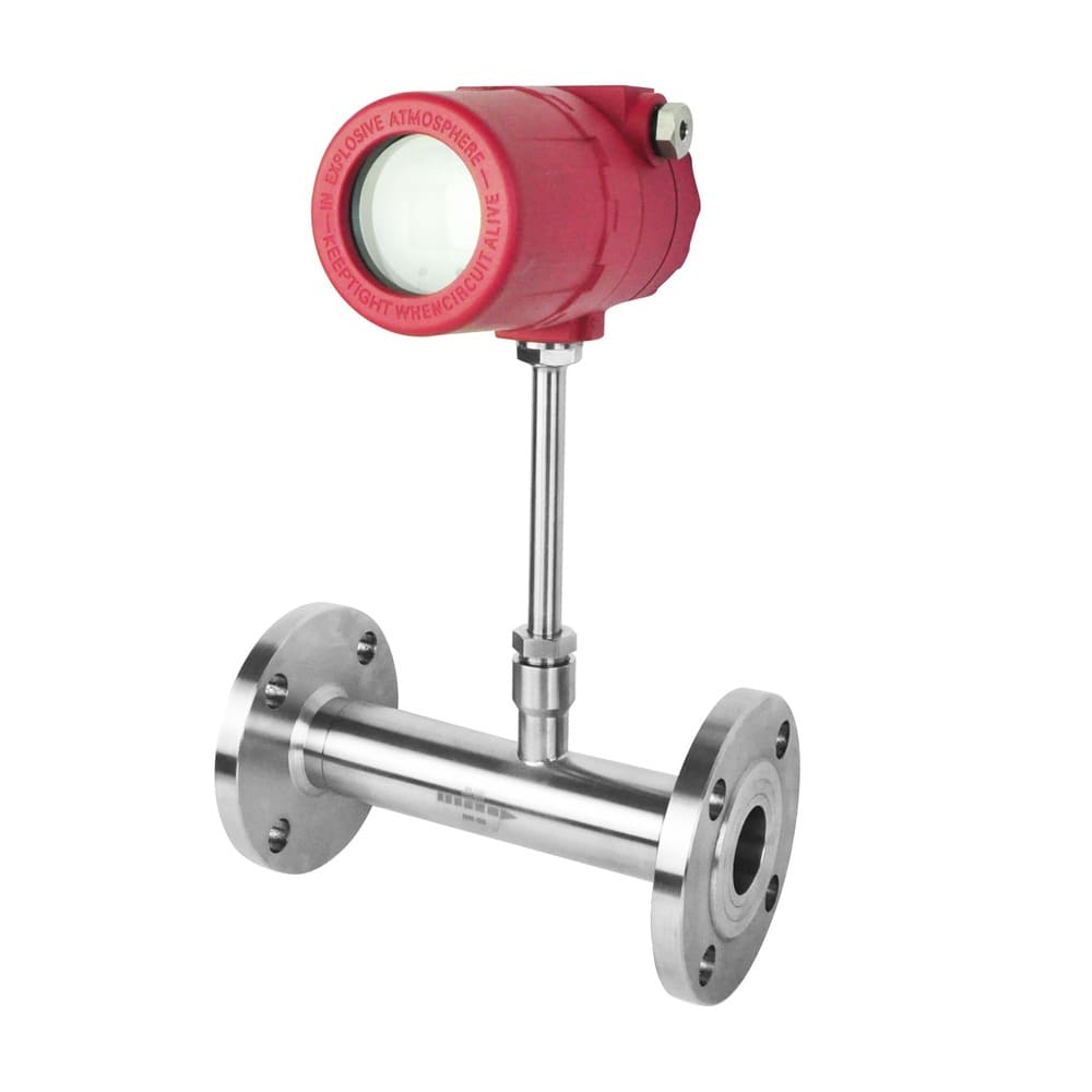
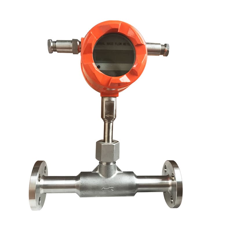
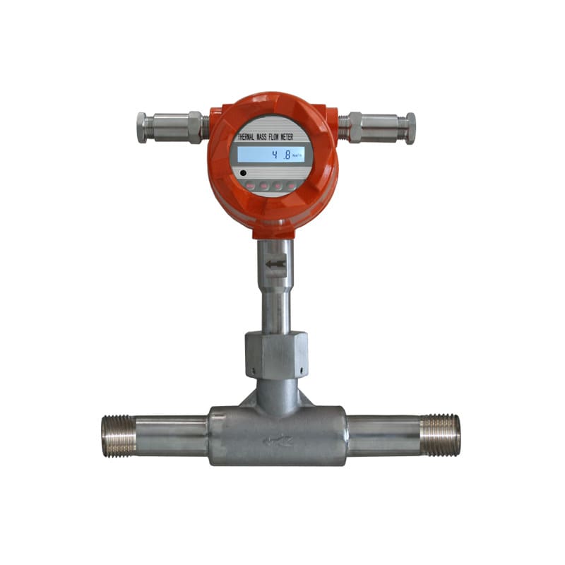
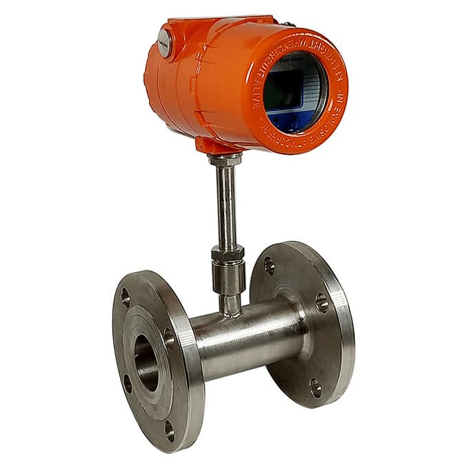
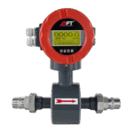
Inline Thermal Mass Flowmeter
Direct mass flow measurement of compressed air, natural gas, and industrial gases—no temperature or pressure compensation required.
Precision mass flow measurement for gases using thermal dispersion technology—heated sensor directly measures molecular mass flow rate in standard units (kg/h, SCFM, Nm³/h) without requiring separate temperature and pressure compensation. Ideal for natural gas billing, process gas control, industrial gas consumption tracking, and air monitoring,
- Pipe Size: DN6 – DN300 (¼" – 12")
- Mass Flow Accuracy: ±1% to ±2% of reading
- Turndown Ratio: 100:1 (measures from 1% to 100% range)
- Gas Types: Air, nitrogen, oxygen, argon, natural gas, CO₂
- Temperature: -40°C to +200°C (process gas)
- Pressure: Up to 10 MPa (100 bar)
Request QuotationTechnical Consultation
True Mass Flow Measurement Without Compensation Calculations
- True mass measurement—no P/T compensation required
- 100:1 turndown ratio—10x better than traditional meters
- 10-year calibration interval—minimal maintenance costs
- <1 second response—real-time process control capability
Parameter | Specification |
|---|---|
Measurement Principle | Thermal dispersion (constant temperature differential method) |
Pipe Size Range | DN6 – DN300 (¼" – 12") |
Mass Flow Accuracy | ±1% of reading (±2% optional for lower cost) |
Repeatability | ±0.2% of reading |
Turndown Ratio | 100:1 (measures 1% to 100% of full scale) |
Gas Compatibility | Air, N₂, O₂, Ar, He, CO₂, CH₄ (natural gas), H₂, gas mixtures. etc |
Process Temperature | 40°C to +200°C (sensor dependent) |
Ambient Temperature | -25°C to +60°C (electronics) |
Process Pressure | 0-10 MPa (0-100 bar, 0-1450 psi) |
Sensor Technology | Twin platinum RTD sensors (heated + reference) |
Connection Type | Flanged (ANSI/DIN), threaded (NPT/BSP for DN6-DN50) |
Output Signals | 4-20mA (isolated), Pulse (mass total), Frequency |
Communication | RS485 Modbus RTU, HART, Profibus DP (optional) |
Display | LCD: mass flow rate, total, temperature, % of full scale |
Displayed Units | kg/h, SCFM, Nm³/h, lb/min (mass), m/s (velocity) |
Data Logging | 10,000+ records internal memory (optional) |
Protection Rating | Sensor: IP65/IP67 | Electronics: IP65 |
Calibration | Factory calibrated for specific gas, multi-gas capable with conversion |
Quality Certifications | CE |
Why Mass Flow Matters More Than Volume
vs. Orifice Plates:
- No pressure/temperature compensation required
- 100:1 turndown vs 3:1 (30x better range)
- No differential pressure transmitter failures
- Minimal pressure drop (<0.5 psi vs 5-20 psi)
- No beta ratio calculation errors
- Higher initial cost (ROI: 2-4 years on energy savings)
vs. Turbine Meters:
- No moving parts (no bearing wear)
- Works in dirty gas (no blade fouling)
- 100:1 turndown vs 10:1 range
- True mass vs volume requiring compensation
- Slower response time for liquid (gas response comparable)
vs. Vortex Shedding:
- Better low-flow accuracy (1% vs 10% minimum)
- No bluff body to create pressure drop
- Works in pulsating flow
- Immune to vibration interference
- Requires clean, dry gas (vortex more tolerant of moisture)
vs. Coriolis Mass:
- 70-80% lower cost for gas applications
- No density errors from gas composition changes
- Simpler installation (no vibration isolation)
- Lower accuracy (±1% vs ±0.1% for Coriolis)
- Gas-specific calibration (Coriolis measures any fluid)
Proper installation ensures accuracy and long-term reliability
Location Selection
- Straight Pipe: Minimum 5D upstream, 3D downstream. Increase to 10D/5D after elbows, valves, or flow disturbances.
- Orientation: Horizontal preferred. Vertical acceptable if flow upward (prevents condensate accumulation on sensor).
- Accessibility: Position for easy sensor inspection and electronics access. Allow space for removal if maintenance required.
Pipe Preparation
- Cleanliness: Remove pipe scale, welding slag, thread sealant residue before installation. Foreign material can damage sensor.
- Dry Gas: Ensure gas dew point <-20°C at operating pressure. Moisture causes measurement error and sensor corrosion.
- Filters: Install 40-100 mesh filter upstream for dirty gas applications. Protects sensor from particulate damage.
Mechanical Installation
- Flanged (DN25-DN300): Install between pipe flanges with proper gaskets. Torque bolts in star pattern per flange rating.
- Threaded (DN6-DN50): Use PTFE tape or thread sealant rated for gas service. Support meter weight independently.
- Flow Direction: Verify arrow on meter body aligns with gas flow direction. Reversed flow causes negative readings.
Electrical Connection
- Power: Connect 24V DC (polarity-sensitive) or 85-265V AC per specifications.
- Outputs: Wire 4-20mA to receiving instruments (observe + and – terminals). Connect pulse/RS485 as required.
- Grounding: Ground meter body to facility ground. Essential for electrical safety and noise immunity.
Ready to Optimize Your Gas Flow Monitoring?
Submit your application parameters and receive a professional model recommendation, datasheet, and competitive quotation from our instrumentation specialists.
info@hbmeter.cc
(+86) 152-3780-0315
1 Jingsan North Road, Xiangfu District, Kaifeng, Henan 475004 China
About HBmeter
AFT Instruments is a high-tech manufacturer delivering precision flow instrumentation for water, chemical, power, industrial automation, and process industries.
View more
Contact Us
info@hbmeter.cc
(+86) 152-3780-0315
(+86) 152-3780-0315
Related Products
Integrated Magnetic Flowmeter
Battery-Powered Magnetic Flowmeter
threaded Magnetic Flowmeter