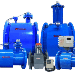

Magnetic Open Channel Flowmeter
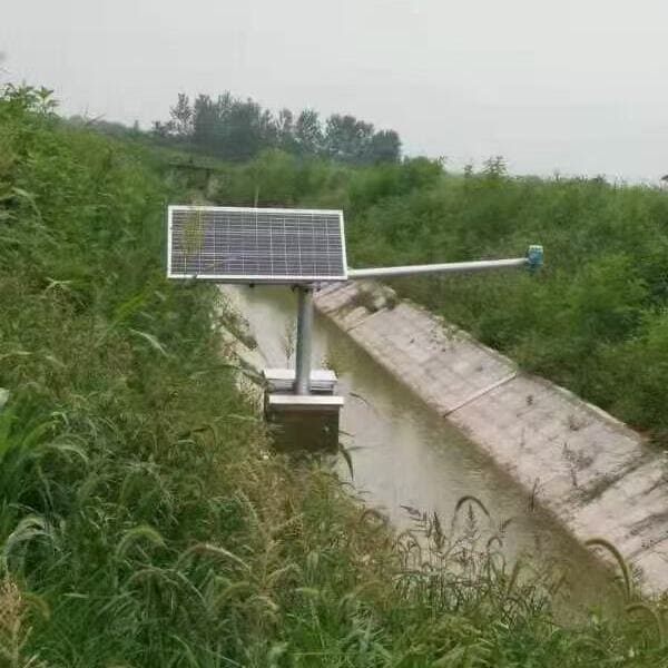
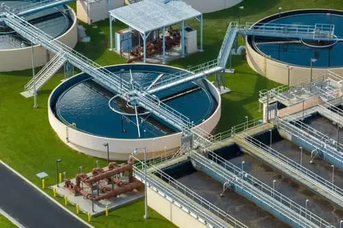
Accurate flow measurement in open channels, canals, and non-pressurized systems without weirs or flumes—using electromagnetic velocity sensing combined with ultrasonic level measurement to calculate flow via the velocity-area method. Ideal for municipal stormwater monitoring, agricultural irrigation districts, wastewater treatment plants, and any application requiring flow measurement in rectangular channels, trapezoidal ditches, or circular pipes flowing partially full.
- Measure width: 40cm – 2000cm
- Flow Accuracy: ±2.5% of reading
- Velocity Range: 0.02 – 10 m/s
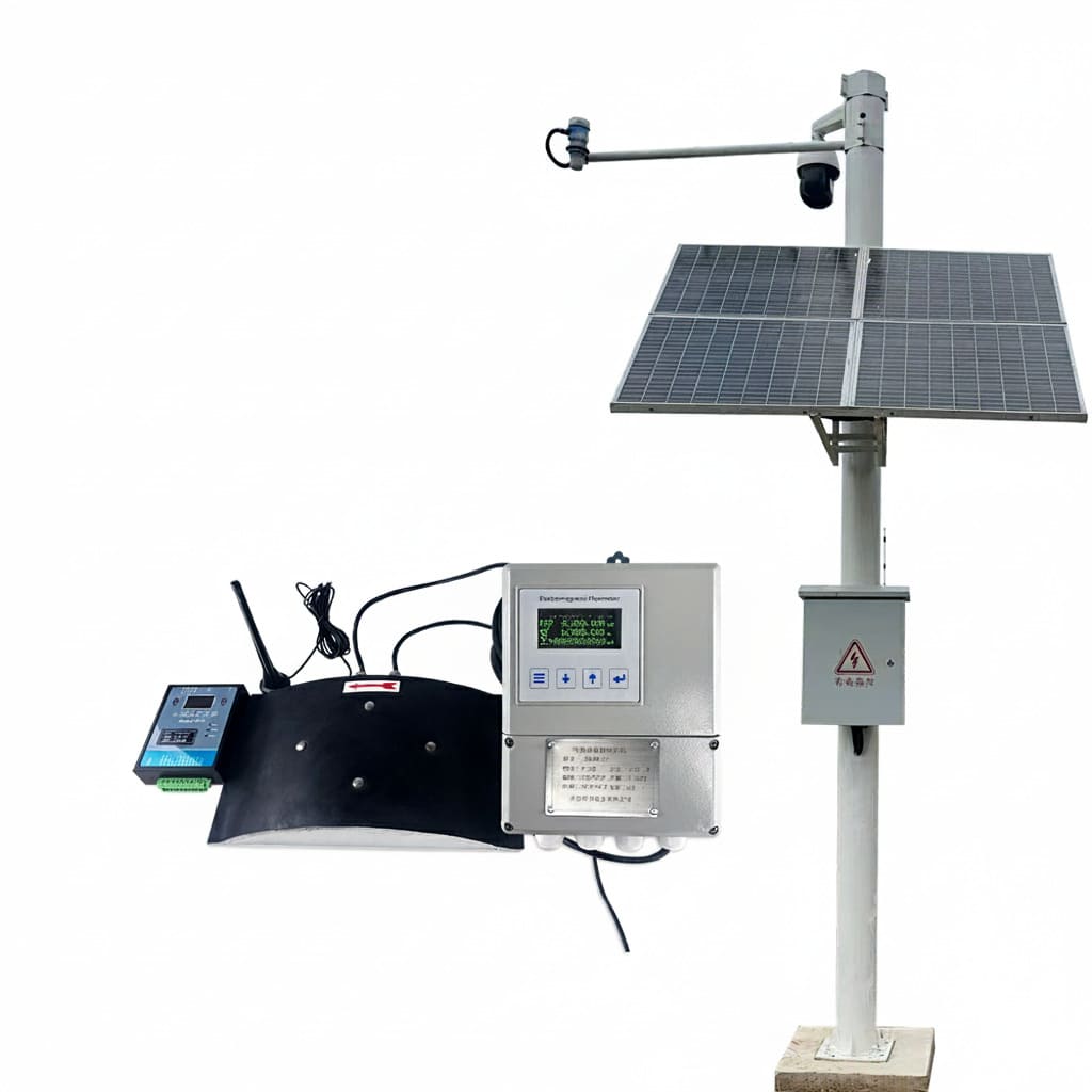
- Power: 220V AC or 12V DC / Solar + Battery
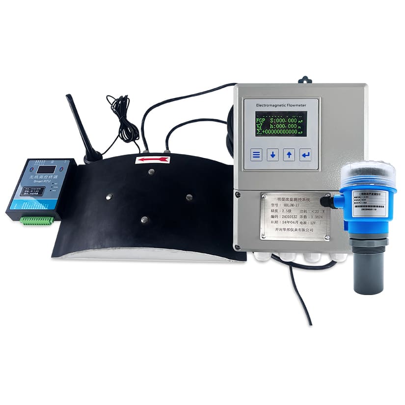
- Display: Flow rate, level, velocity, accumulated volume
Request QuotationTechnical Consultation
Measure Open Channel Flow Without Weirs or Flumes
- 60-75% cost reduction vs. weir/flume installation
- 1:500 measurement range—one sensor handles all flow conditions
- Minimal maintenance—no weir clogging or sediment accumulation
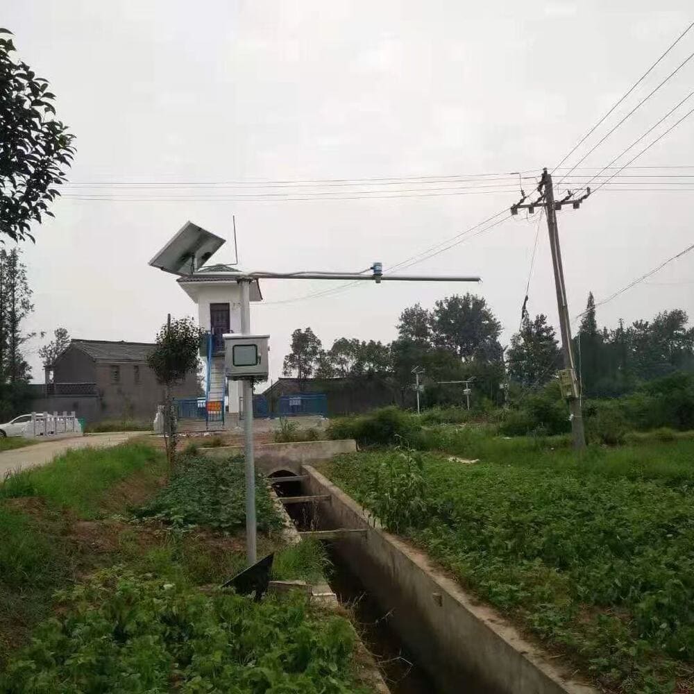
- Flexible Installation—measure flow in existing infrastructure
Parameter | Specification |
|---|---|
Measurement Principle | Velocity-area method: electromagnetic velocity × ultrasonic level |
Application | Open channels, canals, partially filled pipes, ditches, streams |
Channel Size Range | 100mm – 6000mm (width or diameter) |
Channel Shape | Rectangular, trapezoidal, circular, U-shape, custom profiles |
Flow Accuracy | ±2.5% of reading (under ideal conditions) |
Repeatability | ±1.0% of reading |
Level Accuracy | ±2mm or ±0.2% (whichever is greater) |
Velocity Range | 0.02 – 10 m/s (bidirectional measurement) |
Level Measurement Range | 10mm – 5000mm (sensor-dependent) |
Fluid Temperature | -25°C to +60°C |
Velocity Sensor | Electromagnetic (Faraday's Law), flush-mount in channel bottom |
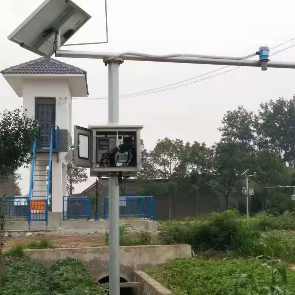
Level Sensor | Ultrasonic (non-contact) mounted above maximum water level |
Power Supply | 220V AC (standard) | 12V DC | Solar panel + battery (off-grid) |
Output Signals | 4-20mA, RS485 Modbus, Pulse, Relay (alarm) |
Communication Protocols | Modbus RTU, GPRS/4G wireless (optional), NB-IoT (optional) |
Data Logging | 10,000+ records internal memory, SD card expansion |
Display | LCD: instantaneous flow, level, velocity, accumulated volume, alarms |
Protection Rating | Velocity sensor: IP68 | Level sensor: IP67 | Converter: IP65 |
Cable Length | Standard 10m (velocity sensor to converter), custom lengths available |
Quality Standards | CE Certification |
Protection Class Section:
- IP65: Dust-tight, protected against water jets—suitable for general industrial environments
- IP68: Dust-tight, continuous submersion—suitable for underground slurry pipelines, wet environments, up to 3 meters depth
Accurate flow data for water management, environmental monitoring, and regulatory compliance
Stormwater Management & CSO Monitoring
- Urban stormwater system monitoring
- Combined sewer overflow (CSO) measurement
- Stormwater BMP performance verification
- Green infrastructure monitoring
- I&I (inflow & infiltration) quantification
Irrigation Districts & Agricultural Water
- Canal and lateral flow measurement
- Water rights allocation and verification
- Irrigation district billing
- Water delivery scheduling
- Crop water use tracking
- Agricultural drainage monitoring
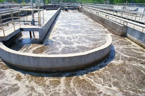
Wastewater Treatment Plants
- Plant influent flow monitoring
- Primary clarifier overflow
- Secondary effluent discharge
- RAS (Return Activated Sludge) flow and WAS (Waste Activated Sludge) flow
- Aeration basin recirculation
- Final effluent compliance monitoring
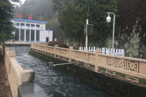
Environmental & Hydrological Monitoring
- Stream flow gauging stations
- Wetland water balance studies
- Groundwater discharge monitoring
- Ecological flow requirements
- Fish passage monitoring
- Watershed research
Mining & Industrial Discharge
- Mine dewatering discharge
- Process water drainage
- Industrial effluent monitoring
- Cooling water discharge
- Settling pond overflow

Proper sensor placement ensures accurate and reliable measurement
Step 1: Site Selection
- Straight Channel Section: Select location with minimum 10× channel width straight section upstream, 5× downstream. Avoid turbulence from bends, structures, or inflows.
- Uniform Cross-Section: Channel geometry must be consistent through measurement section. Avoid transitions, expansions, or contractions.
- Stable Bottom: Velocity sensor requires solid mounting surface. Avoid locations with active scour or sediment deposition.
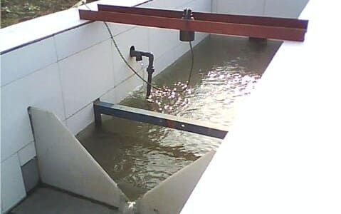
Step 2: Velocity Sensor Installation
- Mounting Position: Install flush with channel bottom, centered in channel width. For wide channels (>3m), consider multiple sensors.
- Sensor Orientation: Flow direction arrow must align with flow. Electrodes positioned horizontally (perpendicular to flow).
Step 3: Level Sensor Installation
- Mounting Height: Position sensor above maximum expected water level plus 500mm safety margin. Sensor must never be submerged.
- Alignment: Beam must point straight down perpendicular to water surface. Verify with plumb line or laser level.
- Obstruction-Free Zone: Ensure no pipes, rails, or structures within beam cone. Minimum 300mm clearance from channel walls.
Step 4: Converter Setup
- Channel Geometry Entry: Program channel shape, dimensions, and slope. Verify wetted area calculation at test depth.
- Sensor Configuration: Set velocity sensor K-factor, level sensor range and offset. Verify sensor readings.
- Output Scaling: Configure 4-20mA and pulse outputs for downstream systems. Set alarm thresholds.
Critical Requirements
- Sensor Placement: Velocity sensor must be at location representing mean channel velocity. Avoid dead zones, eddies, or non-uniform flow areas.
- Level Sensor Range: Select ultrasonic range exceeding maximum level by 50%. Undersized sensors cannot measure peak flows.
- Grounding: Both sensors must be properly grounded. Use grounding rods if channel is non-metallic.
- Cable Protection: Route cables in conduit. Seal all entries to prevent moisture ingress. Use drip loops at low points.
Accurate Open Channel Flow Measurement Without Weirs or Flumes
Measure flow in your channels, canals, or ditches without expensive civil construction. Contact us with channel dimensions and flow range—receive system recommendations and pricing within 24 hours.
info@hbmeter.cc
(+86) 152-3780-0315
1 Jingsan North Road, Xiangfu District, Kaifeng, Henan 475004 China
About HBmeter
AFT Instruments is a high-tech manufacturer delivering precision flow instrumentation for water, chemical, power, industrial automation, and process industries.
 View more
Contact Us
info@hbmeter.cc
(+86) 152-3780-0315
(+86) 152-3780-0315
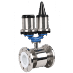
Related Products
Integrated Magnetic Flowmeter
Battery-Powered Magnetic Flowmeter
threaded Magnetic Flowmeter