
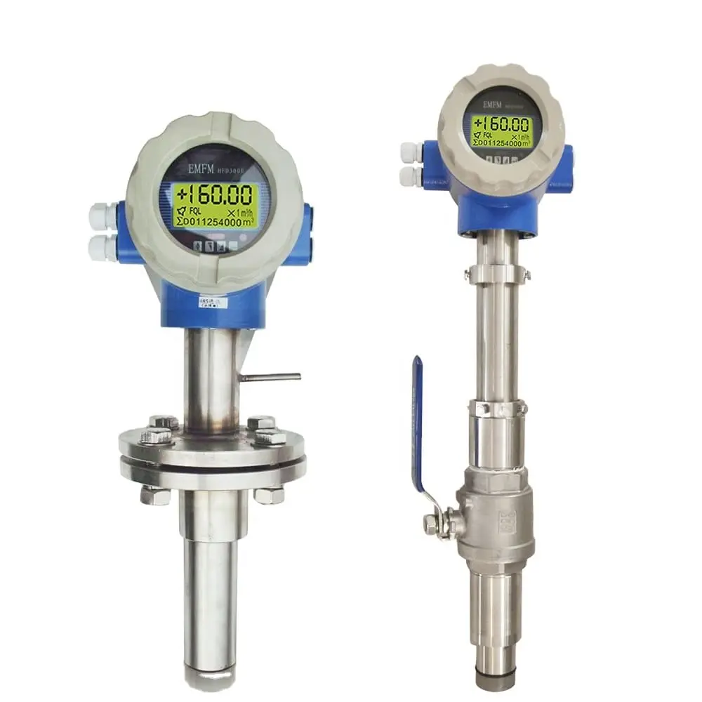
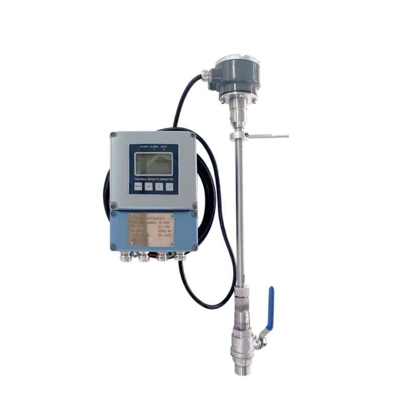
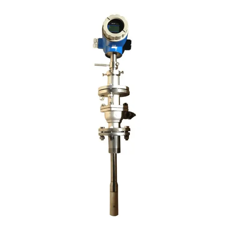
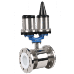
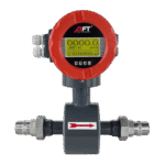
Insertion Electromagnetic Flowmeter
Cost-effective flow measurement for medium-to-large diameter pipelines—this flowmeter inserts through a ball valve into existing pipes from DN100 to DN3000 without system shutdown or pipe cutting. Unlike full-bore electromagnetic flowmeters that require costly removal and reinstallation, the insertion design enables hot-tap installation under pressure, measures flow at the optimal velocity point, and delivers ±1.5% to ±2.5% accuracy at a fraction of the cost—ideal for retrofitting water treatment plants, industrial process lines, and municipal distribution networks where downtime is prohibitive and full-bore meters are economically impractical.
- Pipe Size: DN100 – DN3000
- Flow Accuracy: ±1.5% / ±2.0% / ±2.5% (selectable)
- Velocity Range: 1 – 10 m/s (continuously adjustable)
- Temperature: -25°C to +80°C
- Pressure: 0.6 – 1.6 MPa
- Protection: IP65/IP67/IP68 sensor (optional) | IP65 converter
Request QuotationTechnical Consultation
Large-Pipe Flow Measurement Without the Large-Pipe Cost
Five reasons insertion design outperforms full-bore flowmeters for medium and large-diameter applications
- Zero downtime installation—system remains fully operational during meter commissioning
- Same measurement performance at a fraction of the cost for pipes >DN400
- Selectable accuracy grades for optimal cost-performance balance
- Off-grid measurement capability—no power infrastructure required
- Maintenance windows reduced from days to hours—no system shutdown required
Parameter | Specification |
|---|---|
Measurement Principle | Electromagnetic (Faraday's Law) - point velocity measurement |
Pipe Size Range | DN100 – DN3000 (closed pipeline applications) |
Flow Accuracy | ±1.5% / ±2.0% / ±2.5% of reading (selectable accuracy classes) |
Velocity Range | 1 – 10 m/s (continuously adjustable full scale) |
Fluid Temperature | -25°C to +80°C |
Operating Pressure | 0.6 – 1.6 MPa |
Sensor Body Material | 304 or 316 stainless steel (optional) |
Liner Materials | ABS (standard), PTFE (optional for chemical resistance) |
Electrode Materials | 316L, Hastelloy B, Hastelloy C, Titanium, Tantalum, Platinum-Iridium, Tungsten Carbide Coated |
Power Supply Options | 85-250V AC (45-63Hz), 20-36V DC, 3.6V Battery (DN100-DN1000 only) |
Output Signals | 4-20mA, Frequency, Pulse, RS485 Modbus |
Communication Protocols | Modbus RTU (standard) | HART (optional) | Profibus DP (optional) |
Protection Rating | Sensor: IP65 / IP67 / IP68 (selectable) | Converter: IP65 |
Display | Digital display: flow rate, velocity, totalized volume |
Excitation Mode | Low-frequency square wave excitation |
Configuration Options | Integrated type (sensor + converter combined), Split type (remote converter) |
Explosion-Proof | SIL-3 Certification |
Quality Standards | CE Certification |
Liner & Electrode Material Selection Guide
Sensor Materials for Process Compatibility
Select liner and electrode materials matched to fluid chemistry and temperature
Liner Materials Table:
Lining Material | Temperature Range | Best Applications |
|---|---|---|
ABS Plastic | -25°C to +80°C | Standard sensor head material - cost-effective for most water, wastewater, and neutral process fluids |
PTFE | -25°C to +80°C | Strong acids, alkalis, organic solvents, high-purity chemicals requiring non-contaminating contact |
Electrode Materials Table:
Electrode Material | Corrosion Resistance | Typical Applications |
|---|---|---|
316L Stainless Steel | General purpose, moderate corrosion resistance | Potable water, municipal wastewater, neutral industrial process water, cooling water |
Hastelloy B | Excellent for non-oxidizing acids | Hydrochloric acid (all concentrations), reducing chemical environments |
Hastelloy C | Superior for oxidizing acids and chlorides | Sulfuric acid, chromic acid, ferric chloride, wet chlorine, hypochlorite solutions |
Tantalum | Excellent for chlorides and seawater | Seawater, brackish water, sodium hypochlorite, brine, desalination plants |
Tantalum | Extreme corrosion resistance | Highly corrosive acids, pharmaceutical chemicals, HCl/H₂SO₄ mixtures, aqua regia |
Platinum-Iridium Alloy | Universal chemical resistance | Ultra-pure water systems, semiconductor manufacturing, research laboratories |
Tungsten Carbide Coated Stainless Steel | Erosion resistance for abrasive fluids | Slurries, wastewater with suspended solids, fluids containing sand or particulates |
Note: Electrode material selection critical for long-term reliability. Contact factory for fluid compatibility guidance.
Protection Class Section:
-
IP65 (Standard – Converter & Basic Sensor): Dust-tight, protected against water jets—suitable for indoor installations and weather-protected outdoor location
-
IP67 (Optional – Sensor): Dust-tight, withstands temporary immersion up to 1 meter—suitable for installations subject to occasional flooding or spray washdown
-
IP68 (Optional – Sensor): Dust-tight, continuous submersion rated—suitable for underground wet wells, permanently submerged installations, flood-prone environments
Optimized for Medium and Large-Diameter Flow Measurement
Cost-effective metering where full-bore flowmeters are economically impractical
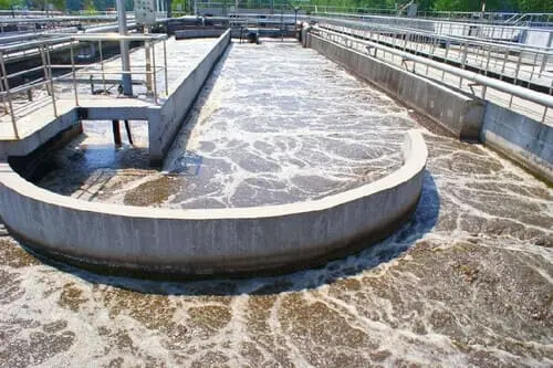
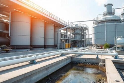
Municipal Water & Wastewater
- Water treatment plant process monitoring
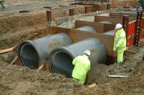
- Distribution main flow measurement
- Wastewater influent/effluent metering
- Pumping station performance monitoring
- Large-diameter trunk sewers
- Water balance and loss detection programs
Chemical & Industrial Processing
- Large-diameter process water lines
- Cooling water circulation systems (DN400-DN3000)
- Reactor feed and discharge lines
- Chemical transfer pipelines
- Inter-plant transfer metering
- Process cooling and heating loops
Power Generation & HVAC
- Condenser cooling water flow
- Circulating water pump monitoring
- Boiler feed water measurement
- Chilled water plant monitoring (DN500-DN2000)
- District heating/cooling systems
- Thermal power plant process water
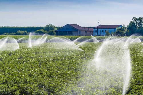
Irrigation & Agricultural Water
- Main irrigation line flow measurement
- Agricultural water district metering
- Water rights allocation and monitoring
- Large-diameter canal and ditch flow
- Reservoir discharge measurement
- Groundwater pumping station flow
Mining & Construction Dewatering
- Mine water pumping systems
- Mine water pumping systems
- Quarry water management
- Tailings transfer pipelines (with tungsten carbide electrodes)
- Underground water drainage
- Remote pit dewatering stations (battery-powered)
Simple Installation for Existing Pipelines
Retrofit capability without system modification or extended downtime
1. Installation Structure Options
- Simple Type: Direct insertion through welded mounting base. Most economical option for new installations or retrofit projects where ball valve can be installed during scheduled shutdown.
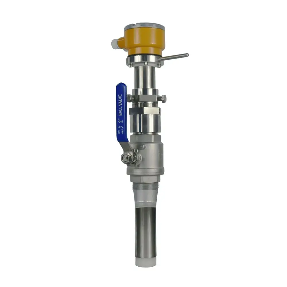
- Threaded Ball Valve Type: DN50 threaded ball valve assembly. Suitable for smaller pipe sizes (DN100-DN600) and lower-pressure applications. Enables sensor removal for maintenance without complete valve disassembly.
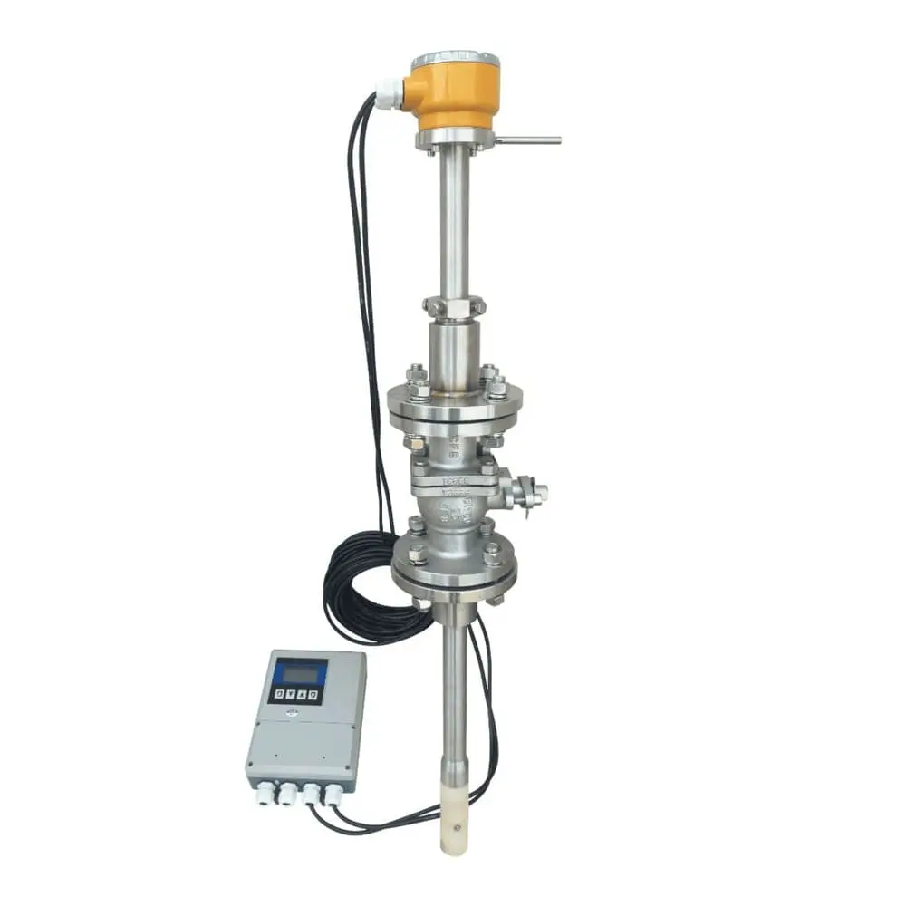
- Flanged Ball Valve Type: Full-flanged DN50 ball valve with standard ANSI/DIN flange connections. Preferred for larger pipes (DN600-DN3000) and higher-pressure applications up to 1.6 MPa. Available in both integrated type (sensor and converter combined) and split type (remote converter mounting) configurations.
2. Critical Installation Requirements
Reduced Straight Pipe Requirements
Unlike many flowmeter types requiring 10D-20D straight pipe, insertion electromagnetic flowmeters need only:
- 5DN upstream (where N = nominal diameter in mm)
- 3DN downstream
- For installations after pumps, valves, or double bends, increase to 10DN upstream when possible
Sensor Orientation
Directional indicator arm must align with flow direction within ±5°. Magnetic field, flow velocity, and electrode axis must be mutually perpendicular per Faraday’s law. Incorrect orientation causes systematic measurement error.
Grounding For metallic pipes:
Ground sensor through pipe flange connection. Verify electrical continuity between sensor body (304/316 SS) and pipe. For non-metallic or lined pipes: Install grounding electrode. Connect to sensor ground terminal (Terminal C). Maintain grounding resistance <10Ω.
Configuration Selection
- Integrated Type: Sensor and converter form single unit. Simplifies installation, reduces cable connections. Suitable when converter can be mounted at pipe location.
- Split Type: Remote converter mounting up to 50m from sensor. Preferred when:
-
- Pipe location is inaccessible or hazardous
- Converter needs protection from weather/vibration
- Multiple sensors controlled from central location
- Existing control room infrastructure available
Ready to Reduce Your Large-Pipe Metering Costs?
Our application engineers will help you determine optimal sensor positioning, accuracy class selection, and configuration requirements for your specific pipeline.
info@hbmeter.cc
(+86) 152-3780-0315
1 Jingsan North Road, Xiangfu District, Kaifeng, Henan 475004 China
About HBmeter
AFT Instruments is a high-tech manufacturer delivering precision flow instrumentation for water, chemical, power, industrial automation, and process industries.
 View more
Contact Us
info@hbmeter.cc
(+86) 152-3780-0315
(+86) 152-3780-0315
Related Products
Integrated Magnetic Flowmeter
Battery-Powered Magnetic Flowmeter
threaded Magnetic Flowmeter