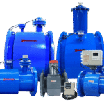

Electromagnetic BTU Meter
Precision Energy Metering for District Heating and Cooling Systems
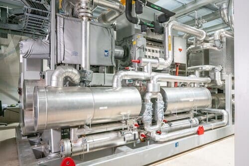
Precise thermal energy measurement for district heating, district cooling, and HVAC applications —combining proven electromagnetic flow measurement technology with precision temperature sensing to deliver accurate thermal energy metering for district heating, central heating, cooling systems, and HVAC applications. By measuring flow rate and temperature differential simultaneously, this integrated system calculates heat energy consumption with ±0.5% accuracy—essential for energy billing, system optimization, and consumption monitoring.
- Pipe Diameter:: DN10 – DN600
- Energy Accuracy: ±(2% + 3%) combined (Class 2 EN 1434)
- Flow Accuracy: ±0.5% of reading
- Temperature Range: 2°C – 150°C (water systems)
- Energy Units: kWh, MWh, GJ, Gcal, MBtu
- Display: Heat, cooling, volume, power, temperature differential
Request QuotationTechnical Consultation
Accurate Energy Billing and Allocation for Thermal Systems
Four reasons electromagnetic technology outperforms mechanical heat meters in commercial and industrial applications
- EN 1434 Class 2 certified—approved for custody transfer billing
- Zero maintenance drift—accuracy stable for 10-15 year service life
- 1:100 turndown ratio—10x better than mechanical meters at low flows
- Remote data access—eliminate manual meter reading site visits
Parameter | Specification |
|---|---|
Measurement Principle | Electromagnetic flow + matched temperature sensors |
Application | Heat measurement, cooling measurement, combined heat/cooling |
Pipe Size Range | DN10 – DN600 |
Energy Accuracy | Class 2 per EN 1434: ±(2% + 3%) combined error |
Flow Accuracy | ±0.5% of reading |
Temperature Accuracy | ±0.1°C (matched PT100/PT1000 pair) |
Fluid Temperature | 2°C – 150°C (water and glycol solutions) |
Temperature Differential (ΔT) | 3°C – 120°C |
Velocity Range | 0.01 – 10 m/s |
Turndown Ratio | 1:100 (qp to qi) |
Operating Pressure | 1.6 MPa (PN16 standard) | 2.5 MPa (PN25 optional) |
Fluid Conductivity | ≥ 20 μS/cm (deionized water requires special configuration) |
Energy Units | kWh, MWh, GJ, Gcal (kcal×10⁶), MBtu (selectable) |
Display Parameters | Thermal energy, cooling energy, volume, flow rate, supply/return temp, ΔT, thermal power |
Power Supply | 85-265V AC or 12-36V DC | 3.6V Battery (10-year life) |
Communication | M-Bus (EN 13757), Modbus RTU/TCP, Wireless M-Bus, BACnet, LonWorks (optional) |
Data Storage | 36+ months hourly data, 10+ years monthly totals |
Display | LCD: instantaneous power, accumulated energy, volume, temps, diagnostics |
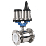
Connection Type | Threaded (DN10-DN60), Flanged (DN65-DN300) |
Protection Rating | Sensor IP65/IP67, Calculator IP54/IP65 |
Explosion-Proof | SIL-3 Certification |
Quality Standards | CE Certification |
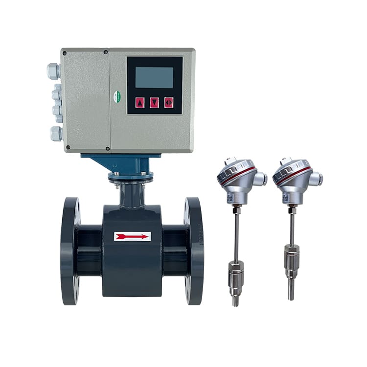
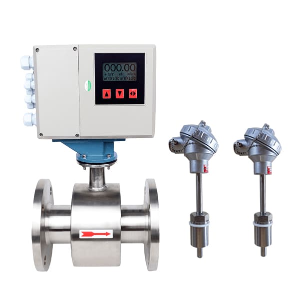
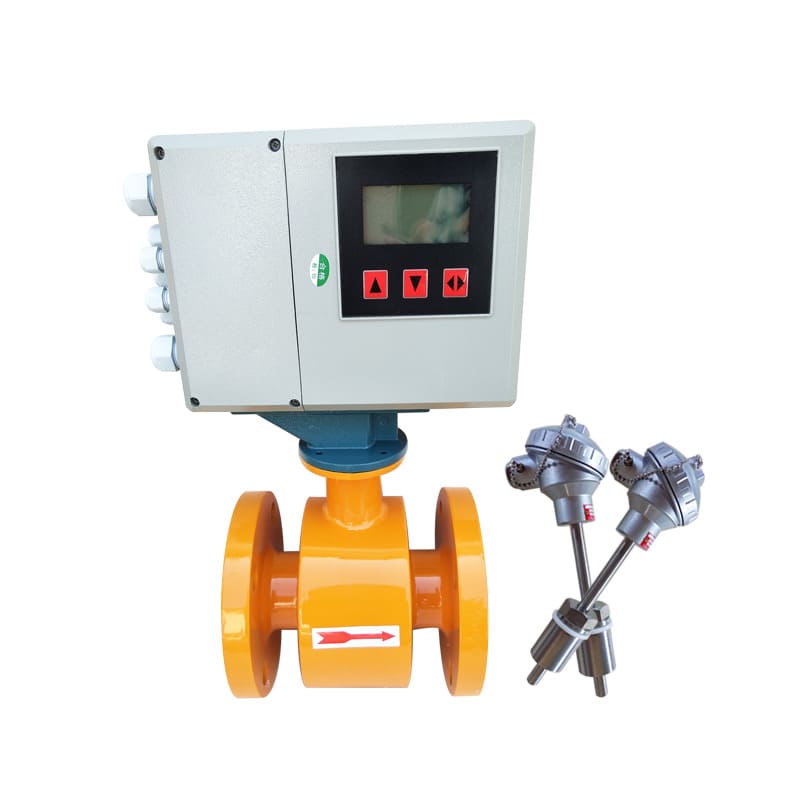
System Configuration Options
Complete Heat/Cooling Metering System Components
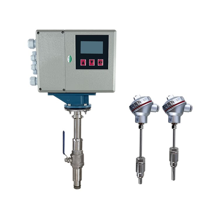
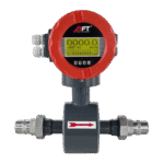
Compact Integrated Configuration (DN10-DN60):
- Flow sensor with integrated calculator
- Threaded connections (NPT, BSP, G-thread)
- Two temperature sensors (supply + return with pockets)
- Single enclosure, minimal space requirement
- Ideal for residential, small commercial applications
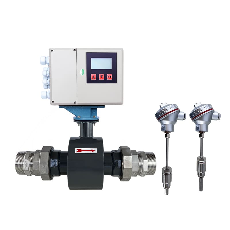
Split Configuration (DN65-DN300):
- Remote calculator up to 30m from flow sensor
- Flanged flow sensor connections
- Wall-mount calculator enclosure
- Multiple sensor inputs (up to 4 systems per calculator)
- Ideal for large commercial, industrial, district energy
Thermal Energy Metering for Heating and Cooling Systems
Accurate energy measurement for district systems, commercial buildings, and industrial processes
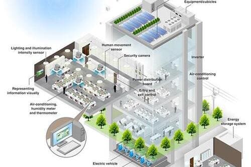
Commercial Building Energy Management
- Tenant submetering and cost allocation
- Chiller plant energy monitoring
- Boiler plant efficiency measurement
- HVAC system performance tracking
- Energy audit and benchmarking
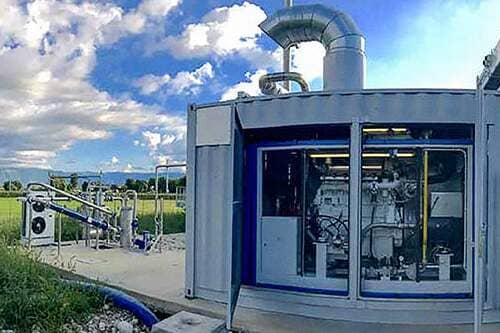
District Heating & Cooling Networks
- District heating/cooling utility billing
- Combined heat and power (CHP) plants
- Customer connection metering
- Thermal energy trading
- Network loss calculation
Industrial Process Heat Monitoring
- Steam condensate return measurement
- Process heating energy consumption
- Thermal oil system monitoring
- Heat recovery system verification
- Process cooling load tracking
- Energy efficiency projects
Multi-Tenant Residential & Mixed-Use
- Apartment building heat allocation
- Condominium association billing
- Mixed-use development submetering
- Property management cost recovery
Institutional & Healthcare Facilities
- Hospital energy management
- University campus steam metering
- Government building monitoring
- Laboratory thermal load tracking
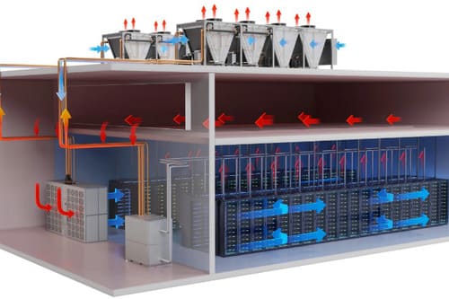
- Data center cooling measurement
Proper installation ensures accuracy and long-term reliability
Step 1: System Design
-
Location: Install flow sensor on supply or return line (return line preferred for longer sensor life). Mount temperature sensors in supply and return lines per manufacturer specification.
-
Pipe Sizing: Select meter size for normal flow in middle 1/3 of velocity range (2-6 m/s optimal). Oversizing reduces accuracy at low loads.
-
Temperature Sensor Position: Install temperature pockets per EN 1434 requirements. Immersion depth minimum 50mm. Ensure adequate straight pipe before and after pockets.
Step 2: Flow Sensor Installation
-
Threaded (DN10-DN60): Use PTFE tape or pipe sealant. Hand-tighten, then wrench-tighten per torque specification. Support piping independently.
-
Flanged (DN60-DN300): Install between pipe flanges. Verify flow direction arrow. Torque bolts in star pattern. Ensure gaskets properly seated.
-
Straight Pipe: Minimum 5D upstream, 3D downstream for rated accuracy. Increase after pumps, valves, or bends.
Step 3: Temperature Sensor Installation
- Pocket Installation: Weld or thread temperature pockets into pipe. Ensure immersion depth per specification. Fill pocket with thermal paste.
- Sensor Installation: Insert PT100/PT1000 sensor into pocket. Secure with compression fitting. Verify sensor pair matching (supply/return sensors must be matched set).
- Cable Routing: Run sensor cables in shielded conduit. Maintain separation from power cables. Label supply and return clearly.
Get precise energy billing and consumption monitoring
Contact us today with your pipe size, temperature range, and application—receive sizing recommendations and pricing within 24 hours.
info@hbmeter.cc
(+86) 152-3780-0315
1 Jingsan North Road, Xiangfu District, Kaifeng, Henan 475004 China
About HBmeter
AFT Instruments is a high-tech manufacturer delivering precision flow instrumentation for water, chemical, power, industrial automation, and process industries.
 View more
Contact Us
info@hbmeter.cc
(+86) 152-3780-0315
(+86) 152-3780-0315
Related Products
Integrated Magnetic Flowmeter
Battery-Powered Magnetic Flowmeter
threaded Magnetic Flowmeter