Compressed Air & Industrial Gases Industry Solutions

Flow Measurement for Every Industrial Gas — from Air Mains to Specialty Gases

Each gas demands a different measurement approach. HBYB thermal mass, gas turbine, and Coriolis instruments cover the full range of industrial gas applications with gas-specific calibration, explosion-proof certification, and direct mass flow output.
Discuss Your Application
What Flow Measurement Covers

From Plant Air Distribution to Specialty Process Gases

Industrial gas measurement spans a wide range of applications — from high-volume compressed air systems to precision dosing of rare specialty gases. Each requires appropriate technology, gas-specific calibration, and the right safety certifications.

Gas measurement is not one-size-fits-all

The same physical meter design does not measure air, hydrogen, and CO₂ with equal accuracy. Gas thermal properties, density, and safety requirements dictate the correct instrument for each gas.

Key Selection Challenges

Six Factors That Determine the Right Gas Flowmeter

Each factor has a direct consequence on measurement accuracy or operational safety when overlooked.

Thermal mass meters require gas-specific calibration

Thermal mass flowmeters work by measuring how much heat a gas absorbs from a heated sensor — and each gas has a unique specific heat capacity and thermal conductivity. A meter calibrated on air measures nitrogen with an error exceeding 5%, and hydrogen with an error exceeding 30%. Every HBYB thermal mass meter must specify the target gas at the time of order for calibration to that gas's thermal properties.
If overlooked: A "gas" flowmeter ordered without specifying the gas type delivers systematically wrong measurements from day one with no visible indication of error.

Volumetric vs. mass flow — the difference matters for billing and control

Gas volume changes with temperature and pressure; mass does not. A volumetric meter on a compressed air main reports different values on a cold morning versus a hot afternoon, even at identical actual consumption. For energy audits, billing, and process control, mass flow (or standard volume Nm³/h at 0°C, 101.3 kPa) is the only meaningful unit. Thermal mass meters and gas turbine meters with T/P compensation both deliver this directly.
If overlooked: Compressed air billing disputes, process recipe errors, and energy benchmarking that shows inconsistent results between seasons without any real change in consumption.

Wide flow range requires meters with high turndown ratios

Industrial compressed air systems operate between near-zero (nights, weekends) and peak production demand — a ratio that easily exceeds 50:1. Most differential pressure meters and some vortex meters cannot measure accurately below 30% of maximum flow. Thermal mass flowmeters achieve turndown ratios up to 200:1 and measure accurately down to 0.5 Nm/s — making them the only technology that captures both standby leakage flow and peak production demand on a single meter range.
If overlooked: Nighttime and weekend consumption — where compressed air leakage is most clearly visible — falls below the meter's minimum, appearing as zero when it is actually the most diagnostic data the system produces.

Hydrogen requires Group IIC explosion-proof certification

Natural gas instruments carry ExdIIBT6 certification — valid for methane, propane, and most hydrocarbons. Hydrogen has a wider flammability range (4–75% in air) and a lower ignition energy than any hydrocarbon, placing it in Explosion Group IIC. An instrument certified only to Group IIB cannot legally be installed in a hydrogen service hazardous area. HBYB hydrogen-service instruments carry ExiaIICT4 certification, which is the correct Group IIC rating for H₂.
If overlooked: Installing an IIB-certified meter in a hydrogen zone is a regulatory violation and a potential ignition source — with liability consequences that extend beyond the instrument to the installation designer.

Oxygen service demands oil-free, oxygen-compatible wetted materials

Oxygen in contact with hydrocarbons (including instrument lubricants) can ignite spontaneously under pressure — a well-documented failure mode called oxygen-fuel ignition. Instruments for oxygen service must use oil-free wetted components, oxygen-compatible seals (PTFE, stainless steel, Hastelloy), and must be assembled and degreased in clean-room conditions. HBYB thermal mass meters for O₂ service are available with oxygen-compatible materials and clean-room preparation on request.
If overlooked: A standard instrument with hydrocarbon-contaminated wetted surfaces installed in an oxygen line is a fire and explosion risk — a category of industrial accident with well-documented catastrophic outcomes.

Large-diameter air mains cannot always be shut down for full-bore installation

Compressed air main headers in active manufacturing facilities often serve multiple production lines simultaneously — shutting them down for full-bore meter installation means shutting down production. Insertion thermal mass flowmeters installed through a hot-tap ball valve fitting solve this entirely: they insert through a single welded port on the existing pipe, can be installed and removed under line pressure, and cover pipes from DN50 to DN2000 without any pipe cutting or production interruption.
If overlooked: Delaying an energy audit or metering project because shutdown cannot be scheduled — losing the energy savings that measurement would have identified for months or years while waiting for an available maintenance window.

Instrument Coverage Map

Where Industrial Gas Measurement Occurs — and Which Meter Applies

From compressor station to point-of-use, this map shows typical gas flow measurement points across an industrial facility and the instrument technologies that serve each stage.
Stage 01
Production & Supply
Compressor outlet
Cylinder manifold
Electrolyzer output
Inline Thermal Mass
Gas Turbine (custody)
Stage 02
Main Distribution
Air ring main
N₂ / O₂ header
H₂ supply main
Insertion Thermal Mass
Hot-tap, no shutdown
Stage 03
Zone & Branch
Production zone air
Process gas branch
Building / area
Inline Thermal Mass
Energy cost allocation
Stage 04
Process Point-of-Use
Machine air supply
Reactor gas feed
Dosing & blanketing
Inline Thermal Mass
Small-bore DN15–DN50
Stage 05
Vent, Flare & Exhaust
Safety vent gas
Exhaust monitoring
Emissions reporting
Insertion Thermal Mass
Wide range, low flow
Thermal Mass Flowmeter (Inline & Insertion)
Gas Turbine Flowmeter (custody & billing)
Coriolis Mass Flowmeter (high-precision specialty)

Find the Right Meter for Your Application

Start with where you're installing — not with the meter type

Select the tab that describes your installation context. Each card shows a specific scenario, the measurement goal, the recommended instrument, and why it fits.
01 - Compressor outlet

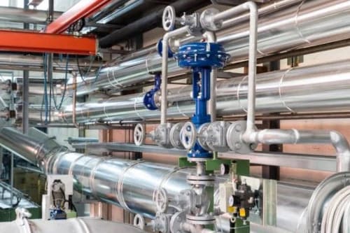
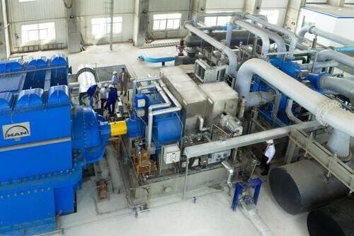
Metering the total air output at the compressor station

The compressor outlet is where energy meets air. Metering here gives you total system consumption, unit energy cost (kWh/Nm³), and the baseline against which every downstream zone is measured. Without this number, you’re managing cost without visibility.

Best fit: Compressor outlet headers DN80–DN300 in existing stations where production shutdown is not an option.
Large-pipe coverage
Nm³/h + cumulative total
BMS / Modbus output
Insertion Thermal Mass Flowmeter
02 - Distribution ring main

Monitoring the plant air ring main and trunk distribution lines

Ring mains distribute compressed air across the facility. Metering key junction points on the ring tells you which direction flow is travelling, whether any segment has a capacity problem, and how much air enters each quadrant of the plant.

Best fit: Ring main junctions and trunk distribution headers DN100–DN600, typically in plant corridors where access is limited.
DN50–DN2000 range
200:1 turndown
Removable under pressure
Insertion Thermal Mass Flowmeter
03 - Multi-compressor comparison

Per-compressor output metering to compare unit efficiency

When a compressor room runs 3–5 units, some are more efficient than others. Metering each unit’s outlet lets you calculate per-unit kWh/Nm³, sequence the most efficient units first, and identify a unit whose efficiency has dropped — before it drives up your electricity bill.

Best fit: Individual compressor outlet branches DN25–DN150, where pipe routing allows inline installation.
Per-unit efficiency data
Direct Nm³/h output
Inline Thermal Mass Flowmeter
01 - Nighttime baseline monitoring

Identifying leaks by monitoring consumption during production shutdowns

The cleanest way to measure leakage in a compressed air system is to watch what happens when production stops. If the compressor keeps running at 1 AM, that flow is pure waste. The technique works when the meter is sensitive enough at low flow to distinguish 50 Nm³/h of leakage from genuine zero. Most DP and vortex meters cannot. Thermal mass meters with 200:1 turndown can — and will capture the exact flow rate, timed and logged, for leak quantification and ROI calculation.

Best fit: Main headers and zone feeds where night-time leakage monitoring is required alongside peak-production measurement on a single meter.
200:1 turndown
Near-zero flow sensitivity
Data logging for audit
Inline Thermal Mass Flowmeter
02 - Temporary field audit

On-site system audits with portable or clamp-on instruments

Not every measurement point needs a permanent meter. An energy audit may require spot-checking dozens of locations over a week, then moving on. Portable clamp-on ultrasonic meters install on the outside of the pipe with no penetration, no shutdown, and no process interaction — move from point to point in minutes. They won’t measure gas as accurately as a calibrated thermal mass meter, but for a comparative audit across multiple branches, they provide the pattern data needed to prioritize where permanent meters go.

Best fit: Compressed air audit surveys where temporary, non-invasive measurement across multiple locations is required before committing to permanent installation.
Zero pipe penetration
Temporary deployment
Portable Ultrasonic Flowmeter
01 - Workshop branch lines

Sub-metering air supply to individual workshops or production lines

When you see total consumption at the compressor but can’t explain where it goes, the answer is zone sub-metering. Meter each workshop feed and the picture becomes clear: you’ll see that the assembly hall uses 40% of your air while the packaging room uses 5% — and whether that ratio makes sense for your production volumes.

Best fit: Workshop feed branches DN25–DN100. Installation via hot-tap if the branch is live; inline if the branch can be briefly isolated.
DN25–DN100
Alarm output
Accumulating totalizer
Per-line tracking
Inline Thermal Mass Flowmeter
02 - Internal billing

Metering for internal utility billing between departments or tenants

Multi-tenant facilities, shared manufacturing parks, and cost-center-driven organizations need defensible, accurate consumption data for internal billing. Meters used for utility billing need reliable long-term drift performance — the difference between an accurate number and a number someone can argue about.

Best fit: Branch lines serving separately billed cost centers or tenants. Accuracy within 1–2% required; totalizer logging essential.
±1.5% accuracy standard
Tamper-evident logging
Long-term stability
Inline Thermal Mass Flowmeter
03 - Pre/post retrofit verification

Measuring before and after a compressor upgrade or system retrofit

Variable frequency drives, heat recovery, pipe network upgrades — efficiency investments only have credibility when the savings are measured. Installing meters before the retrofit gives you the baseline; the same meters after give you the verified saving and the ROI calculation that justifies the next project.

Best fit: Pre-retrofit audits and post-retrofit verification where temporary or permanent installation is needed. Wide flow range required to cover both pre-retrofit waste and post-retrofit efficiency.
Pre/post baseline
Data logging
Wide turndown
Insertion Thermal Mass Flowmeter
01 - Instrument air supply monitoring

Metering instrument air supply to pneumatic valve and control systems

Instrument air is different from general plant air: it’s dried, filtered, and oil-free, and it powers your control system. A drop in instrument air pressure means valve actuators fail, controls lose response, and process safety systems may go to their fail-safe states. Metering the instrument air header gives early warning of a developing shortfall — before a pressure drop causes a control system event. It also makes instrument air cost visible in the utility budget.

Best fit: Instrument air supply headers DN15–DN80, typically small-bore, dry clean gas service. High stability and long service interval required.
Small-bore DN15–DN80
Dry clean gas service
High long-term stability
Intrinsically safe option
Inline Thermal Mass Flowmeter
02 - Control gas sub-metering

Per-system metering of instrument air to critical control zones

Large facilities often have separate instrument air feeds to different control system zones — the reactor building, the utilities block, the packaging hall. Metering each feed separately identifies which zone is consuming unexpectedly (often a seat-leaking valve or a fitting that was never properly tightened) and allows cost attribution by system.

Best fit: Individual instrument air branch feeds to separate control zones, DN15–DN50. Explosion-proof option required in classified areas.
Per-zone tracking
Alarm on excess consumption
Ex-proof available
Inline Thermal Mass Flowmeter
01 - Gas storage & cylinder supply

Monitoring consumption at industrial gas cylinder manifolds and bulk storage

Industrial gas users — whether drawing from cylinder packs, dewars, or bulk tanks — need to meter outflow to track consumption against supply contracts, detect abnormal usage, and plan replenishment. The meter must be calibrated for the specific gas (nitrogen, oxygen, argon, CO₂, hydrogen) and, where the gas is flammable, carry the appropriate explosion-proof certification for the installation zone.

Best fit: Gas outlet from cylinder manifolds or bulk storage headers, DN15–DN80. Gas-specific calibration and material compatibility essential.
Gas-specific calibration
316L SS wetted parts
Nm³/h cumulative total
Ex-proof available
Inline Thermal Mass Flowmeter
02 - Combustion & shielding gas

Metering combustion air, oxygen enrichment, and protective atmosphere gas flows

Combustion-related gas flows — burner air, oxygen enrichment, heat treatment protective atmospheres (N₂/H₂ blends) — require continuous, responsive mass flow measurement. The mass flow rate is the control variable: it determines flame temperature, atmosphere composition, and product quality. Instruments for these applications need wide turndown to follow load swings and fast response to closed-loop control commands.

Best fit: Combustion air headers and protective atmosphere supply lines DN25–DN200. Wide range and fast dynamic response required. Gas-specific calibration mandatory.
Fast dynamic response
T/P auto compensation
Closed-loop compatible
Inline Thermal Mass Flowmeter
03 - High-purity & specialty gas

Small-flow precision measurement for high-purity and specialty process gases

Semiconductor fabs, electronics manufacturers, laboratories, and pharmaceutical plants use small quantities of high-purity or specialty gases — argon for welding atmospheres, helium for leak testing, calibration gas blends — where contamination is not acceptable and measurement accuracy determines process yield. These applications typically require very small-bore instruments (DN10–DN25), high-precision calibration, and materials that will not contaminate the gas.

Best fit: High-purity gas supply at low flow rates, DN10–DN50. Ultra-clean wetted materials and traceable calibration required.
Ultra-clean materials
Traceable calibration
Specialty gas calibration
Inline Thermal Mass Flowmeter

Instrument Requirements

What industrial gas service actually demands

Not features — requirements. The things that are non-negotiable for each gas service type.

Gas-Specific Calibration Certificate

Every HBYB thermal mass meter ships calibrated to the specified gas — air, N₂, O₂, H₂, CO₂, Ar, or mixed. Calibration certificate traceable to national standards is included with every instrument. Specify the gas when you order.

Explosion-Proof Certification

ExdIICT6 Gb for hydrogen and highly flammable gases (Group IIC). ExiaIIBT4 for general hydrocarbon and solvent environments. Check the gas group before specifying — a IIB-certified meter cannot legally be installed in a hydrogen zone.

Direct Nm³/h Output

Standard volume (Nm³/h at 0°C, 101.3 kPa) output is built in — no external flow computer or T/P transmitters required. This is what energy accounting, billing, and process control systems need. Not m³/h at operating conditions.

Material Compatibility

Oxygen service requires oil-free, degreased wetted parts. Hydrogen service requires stainless steel with no elastomers that absorb H₂. Standard compressed air instruments are not automatically suitable for other gases. State your gas type and we confirm compatibility.

Get the Right Meter

Need help matching your application with the right flowmeter?

Tell us your gas, pipe size, pressure, temperature, installation position, and project goal. Our team will recommend the most suitable flowmeter type first, then help narrow down the right model and configuration.
Gas-specific calibration certificate with every instrument
Explosion-proof class confirmed for your installation zone
Direct manufacturer pricing — no distributor margin