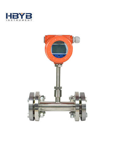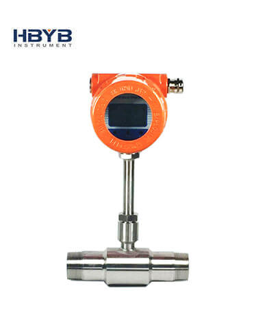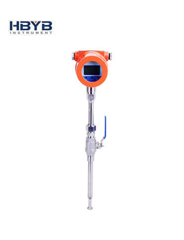


Thermal Gas Mass Flow Meter
Thermal gas mass flow meter is designed on the basis of thermal dispersion, and adopts method of constant differential temperature to measuring gas flow. It has advantages of small size, easy installation, high reliability and high accuracy, etc.
-
Tel:
+86 13353783678 -
E-mail:
info@hbmeter.cc
Product description
The meter contains two platinum resistance temperature sensors. The thermal principle operates by monitoring the cooling effect of a gas stream as it passes over a heated sensor. Gas flowing through the sensing section passes over two sensors one of which is used conventionally as a temperature sensor, whilst the other is used as a heater. The temperature sensor monitors the actual process values whilst the heater is maintained at a constant differential temperature above this by varying the power consumed by the sensor. The greater the gas velocity, the greater the cooling effect and power required to maintain the differential temperature. The measured heater power is therefore a measure of the gas mass flow rate. The format of gas velocity and power is shown as below:

(1)
Where: is specific gravity of medium
V is velocity
K is balance coefficient
Q is heater power
Δ T is differential temperature
The medium temperature range of meter is -40℃~220℃.
In the format (1), the specific gravity of medium is related to the density:

(2)
Where: is the medium density in working condition(kg/m3)
ρn is the medium density in standard condition, 101.325kPa and 20℃ (kg/m3)
P is the pressure in working condition(kPa)
T is the temperature in working condition (℃)
In the formats (1) and (2), there is a certain functional relationship between the velocity and pressure in working condition, medium density, the temperature in working condition.
Due to the sensor temperature is always 30℃ higher than the medium temperature (environment temperature), and the meter adopts method of constant differential temperature, therefore the meter do not need to do temperature and pressure compensation in principle.
Features
- 01Measuring the mass flow or volume flow of gas.
- 02Do not need to do temperature and pressure compensation in principle with accurate measurement and easy operation.
- 03Wide range: 0.5Nm/s~100Nm/s for gas. The meter also can be used for gas leak detection.
- 04Good vibration resistance and long service life. No moving parts and pressure sensor in transducer, no vibration influence on the measurement accuracy.
- 05Easy installation and maintenance. If the conditions on site are permissible, the meter can achieve a hot-tapped installation and maintenance. (Special order of custom-made).
- 06Digital design, high accuracy and stability.
- 07Configuring with RS485 or HART interface to realize factory automation and integration.
technical parameter
| Description | Specifications |
| Measuring Medium | Various gases (Except the acetylene) |
| Pipe Size | DN10~DN4000mm |
| Velocity | 0.1~100 Nm/s |
| Accuracy | ±1~2.5% |
| Working Temperature | Sensor: -40℃~+220℃ Transmitter: -20℃~+45℃ |
| Working Pressure | Insertion Sensor: medium pressure≤ 1.6MPa Flanged Sensor: medium pressure≤ 1.6MPa Special pressure please contact us |
| Power Supply | Compact type: 24VDC or 220VAC, Power consumption ≤18W Remote type: 220VAC, Power consumption ≤19W |
| Response Time | 1s |
| Output | 4-20mA (optoelectronic isolation, maximum load 500Ω), Pulse, RS485 (optoelectronic isolation) and HART |
| Alarm Output | 1-2 line Relay, Normally Open state, 10A/220V/AC or 5A/30V/DC |
| Sensor Type | Standard Insertion, Hot-tapped Insertion and Flanged |
| Construction | Compact and Remote |
| Pipe Material | Carbon steel, stainless steel, plastic, etc |
| Display | 4 lines LCD Mass flow, Volume flow in standard condition, Flow totalizer, Date and Time, Working time, and Velocity, etc. |
| Protection Class | IP65 |
| Sensor Housing Material | Stainless steel (316) |
Upper Range Value of Common Gas
(Unit: Nm3/h. The follow table can be extended)
| Nominal Diameter (mm) | Air | Nitrogen(N2) | Oxygen(O2) | Hydrogen(H2) |
| 15 | 65 | 65 | 32 | 10 |
| 25 | 175 | 175 | 89 | 28 |
| 32 | 290 | 290 | 144 | 45 |
| 40 | 450 | 450 | 226 | 70 |
| 50 | 700 | 700 | 352 | 110 |
| 65 | 1200 | 1200 | 600 | 185 |
| 80 | 1800 | 1800 | 900 | 280 |
| 100 | 2800 | 2800 | 1420 | 470 |
| 125 | 4400 | 4400 | 2210 | 700 |
| 150 | 6300 | 6300 | 3200 | 940 |
| 200 | 10000 | 10000 | 5650 | 1880 |
| 250 | 17000 | 17000 | 8830 | 2820 |
| 300 | 25000 | 25000 | 12720 | 4060 |
| 400 | 45000 | 45000 | 22608 | 7200 |
| 500 | 70000 | 70000 | 35325 | 11280 |
| 600 | 100000 | 100000 | 50638 | 16300 |
| 700 | 135000 | 135000 | 69240 | 22100 |
| 800 | 180000 | 180000 | 90432 | 29000 |
| 900 | 220000 | 220000 | 114500 | 77807 |
| 1000 | 280000 | 280000 | 141300 | 81120 |
| 1200 | 400000 | 400000 | 203480 | 91972 |
| 1500 | 600000 | 600000 | 318000 | 101520 |
| 2000 | 700000 | 700000 | 565200 | 180480 |
Product description
The flow rate in standard condition: The flow rate is in the condition of 20℃ temperature and 101.325kPa pressure.
The unit of flow rate is optional: Nm3/h, Nm3/min, L/h, L/min, t/h, t/min, kg/h or kg/min.
The reduction formula of flow rate in working condition and flow rate in standard condition:

Qs: The flow rate in standard condition (Nm3/h).
Qn: The flow rate in working condition (m3/h).
t: The medium temperature in working condition (℃).
p: The medium pressure in working condition (Gauge pr


