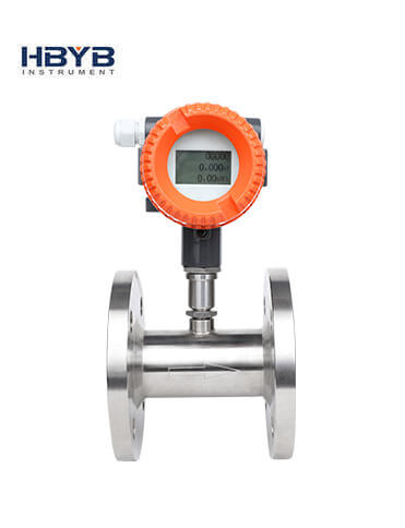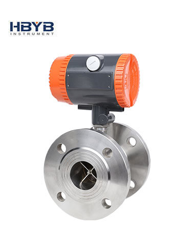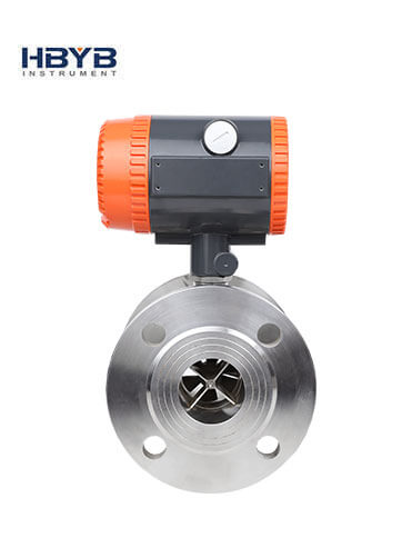


Turbine Flow Meter
The LWGY series turbine flow meter is a new generation of turbine flow meter that has absorbed the domestic and foreign flow meter cash technology and has been optimized and designed.
-
Tel:
+86 13353783678 -
E-mail:
info@hbmeter.cc
Product description
The LWGY series turbine flow meter is a new generation of turbine flow meter that has absorbed the domestic and foreign flow meter cash technology and has been optimized and designed. It has the characteristics of simple structure, light weight, high precision, good reproducibility, responsiveness, easy installation and maintenance, and is widely used. In the measurement of closed pipes, it has no corrosion effect with stainless steel 1Cr18Ni9Ti, 2Cr13 and corundum AI2O3, cemented carbide, and has no impurities such as fibers and particles. The kinematic viscosity at operating temperature is less than 5×10⁻⁶m2/s. For kinematic viscosity greater than 5×10⁻⁶m2/s liquid can be used after the liquid calibration of the flow meter. If it is matched with a display instrument with special functions, it can also perform quantitative control and over-alarm alarm, etc. It is an ideal instrument for flow measurement and energy saving.

1. Housing 2. Flow guide 3. Cone 4. Bearing system 5. Impeller 6. Thrust body 7. Flow guide 8. Long shaft 9. Nut 10. Signal monitor 11. Amplifier
Figure 1 Schematic diagram of LWGY basic liquid turbine flow sensor
Working Principle
(1) When the measured fluid flows through the sensor, under the action of the fluid, the impeller is forced to rotate, its speed is proportional to the average flow rate of the pipe, and the rotation of the impeller periodically changes the reluctance value of the magnetoelectric converter. The magnetic flux in the detection coil then changes periodically, generating a periodic induced potential, that is, an electrical pulse signal, amplified by the amplifier, and sent to the display instrument for display.
(2) Turbine flow meter flow equations can be divided into two types: practical flow equations and theoretical flow equations.
(3) Practical flow equation
qv=f/k
qm=qvρ
In the formula
qv, qm. . . . Respectively, volume flow, m3/s, mass flow, Kg/s;
F....the frequency of the flow meter output number, Hz;
K....the meter factor of the flow meter, p/m3.
(2) The theoretical flow equation
The equation of motion of the impeller can be listed according to the momentum theorem
J=M1-M2-M3-M4
In the formula
J: moment of inertia of the impeller;
dw/dt: rotational acceleration of the impeller;
M1: driving torque of the fluid;
M2: viscous drag torque;
M3: Bearing friction resistance torque;
M4: Reluctance torque.
When the impeller rotates at a constant speed, JX=0, then M1=M2+M3+M4
Available through theoretical analysis and experimental verification
n=Aqv+B-
In the formula
n: impeller speed;
qv: volume flow;
A: With the fluid properties (density, viscosity, etc.), impeller structure parameters
(Blade inclination angle, impeller diameter, flow channel cross-sectional area, etc.) related parameters;
B: Coefficient related to blade tip clearance and fluid velocity distribution;
C: Coefficient related to friction torque.
Features
- 01High accuracy, generally up to ±1%R, ±0.5%R, high precision type up to ±0.2%R;
- 02Good repeatability, short-term repeatability can reach 0.05%~0.2%, precisely because of good repeatability, such as frequent calibration or online calibration can get extremely high accuracy, is the preferred flow meter in trade settlement;
- 03Output pulse frequency signal, suitable for total measurement and computer connection, no zero drift, strong anti-interference ability;
- 04High frequency signal (3~4kHz) can be obtained with strong signal resolution;
- 05Wide range, medium and large caliber up to 1:2, small caliber 1:10;
- 06Compact and lightweight structure, easy installation and maintenance, and large circulation capacity;
- 07High-pressure measurement is used, and there is no need to make holes in the meter body, so it is easy to make a high-pressure meter;
- 08There are many types of special sensors, which can be designed as various special sensors according to the special needs of users, such as low temperature type, bidirectional type, downhole type, sand mixing type, etc.;
- 09Can be made into insert type, suitable for large-diameter measurement, low pressure loss, low price, continuous flow removal, easy installation and maintenance.
technical parameter
| Project | Technical parameter |
| Executive Standard | Turbine flow sensor (JB/T9246~1999) |
| Instrument caliber (mm) and connection method | 4, 6, 10, 15, 20, 25, 32, 40 use screw connection 15, 20, 25, 32, 40) 50, 65, 80, 100, 125, 150, 200 use flange connection |
| Accuracy class | ±1%R, ±05%R |
| Range ratio | 1:10; 1:15; 1:20 |
| Sensor material | 304 stainless steel, 316 (L) stainless steel, etc. |
| Conditions of Use | Medium temperature: -20℃~+120℃ (Explosion-proof type: -20~70℃ ) Ambient temperature: -20℃~+55℃ Relative humidity: 5℃~95℃ Atmospheric pressure: 86Kpa~106Kpa |
| Signal output function | Two-wire output Output low level IOL≈3mA Output high level IOH≈13mA (square wave) Load resistance R (including line impedance) is in the range of 100~500Ω Three-wire output: VOP-P≥5V (square wave) |
| Communication output function | RS485 communication, HART protocol, etc. |
| Working power | A、A. External power supply: +12VAC~+24VDC, shading ≤±5, suitable for 4-20mA output, pulse output, RS485, etc. B、Internal power supply: 1 set of 3.0V10AH lithium battery, the battery voltage can work normally when the voltage is 2.0V~3.0V |
| Signal line interface | Basic type: Hausmann connector or its own three-core cable; explosion-proof type: internal thread M20×1.5 |
| Explosion-proof grade | ExiaIICT4 or ExdIIBT6 |
| Protection class | IP65 or higher (customizable) |
Measuring range and Working pressure
| Instrument caliber (mm) | Normal flow range (m3/h) | Extended flow range (m3/h) | Conventional connection method and pressure rating | Specially made withstand voltage level (Mpa) (flange clamp) |
| DN4 | 0.04~0.25 | 0.04~0.4 | Thread connection / 6.3Mpa | 10、16、25 |
| DN6 | 0.1~0.6 | 0.06~0.6 | Thread connection / 6.3Mpa | 10、16、25 |
| DN10 | 0.2~1.2 | 0.15~1.5 | Thread connection / 6.3Mpa | 10、16、25 |
| DN15 | 0.6~6 | 0.4~8 | Thread connection / 6.3Mpa | 4.0、6.3、10、16、25 |
| Thread connection /2.5Mpa | ||||
| DN20 | 0.8~8 | 0.45~9 | Thread connection/6.3Mpa | 4.0、6.3、10、16、25 |
| Thread connection/2.5Mpa | ||||
| DN25 | 1~10 | 0.5~10 | Thread connection/6.3Mpa | 4.0、6.3、10、16、25 |
| Thread connection/2.5Mpa | ||||
| DN32 | 1.5~15 | 0.8~15 | Thread connection/6.3Mpa | 4.0、6.3、10、16、25 |
| Thread connection/2.5Mpa | ||||
| DN40 | 2~20 | 1~20 | Thread connection/6.3Mpa | 4.0、6.3、10、16、25 |
| Thread connection/2.5Mpa | ||||
| DN50 | 4~40 | 2~40 | Thread connection/2.5Mpa | 40、63、10、16、25 |
| DN65 | 7~70 | 4~70 | Thread connection/2.5Mpa | 40、63、10、16、25 |
| DN80 | 10~100 | 5~100 | Thread connection/2.5Mpa | 40、63、10、16、25 |
| DN100 | 20~200 | 10~200 | Thread connection/1.6Mpa | 2.5、4.0、6.3、10、16、25 |
| DN125 | 25~250 | 13~250 | Thread connection/1.6Mpa | 2.5、4.0、6.3、10、16 |
| DN150 | 30~300 | 15~300 | Thread connection/1.6Mpa | 2.5、4.0、6.3、10、16 |
| DN200 | 80~800 | 40~800 | Thread connection/1.6Mpa | 2.5、4.0、6.3、10、16 |
Product size chart
| Nominal diameter (DN) | Sensor size (mm) | Flange size(mm) | Thread size | |||||||||||||
| L | H | D | D1 | D2 | D3 | n-do | L1(mm) | G | ||||||||
| 4 | 225 | 145 | 1/2 | |||||||||||||
| 6 | 225 | 145 | 1/2 | |||||||||||||
| 10 | 345 | 170 | 1/2 | |||||||||||||
| 15 | 75 | 190 | 95 | 65 | 45 | 4-14 | 23 | 1 | ||||||||
| 20 | 85 | 210 | 105 | 75 | 55 | 4-14 | 23 | 1 | ||||||||
| 25 | 100 | 230 | 115 | 85 | 65 | 4-14 | 30 | 11/4 | ||||||||
| 32 | 120 | 250 | 140/135 | 100 | 78 | 4-18 | 30 | 11/4 | ||||||||
| 40 | 140 | 260 | 150/145 | 110 | 85 | 4-18 | 35 | 2 | ||||||||
| 50 | 150 | 270 | 165/160 | 125 | 100 | 4-18 | ||||||||||
| 65 | 150 | 290 | 185/180 | 145 | 125 | 4-18 | ||||||||||
| 80 | 200 | 300 | 200/195 | 160 | 135 | 8-18 | ||||||||||
| 100 | 220 | 330 | 220/215 | 180 | 155 | 8-18 | ||||||||||
| 125 | 250 | 380 | 250/245 | 210 | 185 | 8-18 | ||||||||||
| 150 | 300 | 390 | 285/280 | 240 | 210 | 8-23 | ||||||||||
| 200 | 360 | 455 | 340/335 | 295 | 265 | 12-23 | ||||||||||
| 250 | 400 | 510 | 405 | 355 | 320 | 12-26/25 | ||||||||||
| 300 | 420 | 565 | 460 | 410 | 375 | 12-26/25 | ||||||||||
| 400 | 560 | 680 | 580 | 525 | 485 | 16-30 | ||||||||||
| 500 | 600 | 790 | 715/705 | 650 | 608 | 20-34 | ||||||||||


