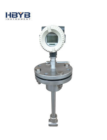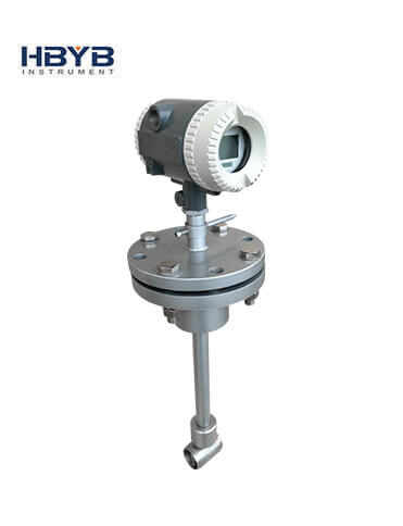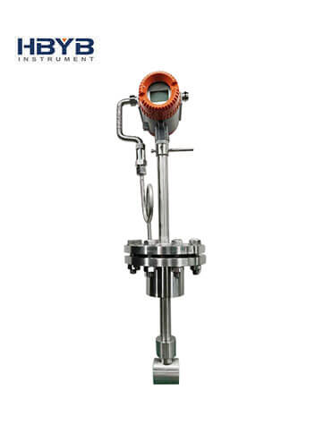


Insert Vortex Flowmeter
The plug-in plug-in vortex flowmeter is mainly used for the flow measurement of industrial pipeline medium fluid, such as gas, liquid, steam and other media.
-
Tel:
+86 13353783678 -
E-mail:
info@hbmeter.cc
Product description
The plug-in plug-in vortex flowmeter is mainly used for the flow measurement of industrial pipeline medium fluid, such as gas, liquid, steam and other media. It is characterized by small pressure loss, large measuring range, and high accuracy. It is hardly affected by fluid density, pressure, temperature, viscosity and other parameters when measuring volume flow under working conditions. There are no movable mechanical parts, so the reliability is high and the maintenance is small. The instrument parameters can be stable for a long time. This instrument adopts piezoelectric stress sensor, which has high reliability and can work in the working temperature range of -25℃~+320℃. It has analog standard signal and digital pulse signal output. It is easy to use with digital systems such as computers. It is a relatively advanced and ideal flow meter.
technical parameter
| Nominal diameter (mm) | 15, 25, 40, 50, 65, 80, 100, 125, 150, 200, 250, 300, (300~1000 plug-in type) |
| Nominal pressure (MPa) | 1.6(>1.6supplied by agreement) |
| Medium temperature (℃) | -40-350℃ |
| Body material | 304SS,(supplied by agreement for other materials) |
| Allowable vibration acceleration | Piezoelectric type:0.2g, Capacitive type:1.0~2.0g |
| Accuracy | ±1%R, ±1.5%R, ±1FS; plug-in: ±2.5%R, ±2.5%FS |
| Range | 1:6~1:30 |
| Supply voltage Sensor | +12V DC, +24V DC; Transmitter: +12V DC, +24V DC; battery-powered type: 3.6V battery |
| Output signal | Square wave pulse (not including battery-powered type): high level ≥ 5V, low level ≤ 1V; current: 4-20mA |
| Pressure loss coefficient | Conforms to JB/T9249 standard Cd≤2.4 |
| Explosion-proof mark | Ex ia IICT6Ga |
| Protection grade | IP65 |
| Environmental conditions | Temperature -20℃~55℃, relative humidity 5%~90%, atmospheric pressure 86~106kPa |
| Applicable medium | gas, liquid, steam, etc. |
| Transmission distance | Three-wire pulse output type: ≤300m, two-wire standard current output type (4~20mA): load resistance ≤750Ω, Flange mounting size chart |
The flange standard of this table is

| Size (mm) |
15 | 20 | 25 | 32 | 40 | 50 | 65 | 80 | 100 | 125 | 150 | 200 | 250 | 300 |
| L (mm) |
95 | 95 | 95 | 114 | 114 | 117 | 117 | 117 | 136 | 151 | 170 | 190 | 205 | 220 |
| H (mm) |
460 | 460 | 460 | 480 | 490 | 500 | 515 | 530 | 550 | 570 | 600 | 650 | 710 | 760 |
| D (mm) |
125 | 125 | 125 | 145 | 145 | 160 | 180 | 195 | 215 | 245 | 280 | 335 | 405 | 460 |
| D1 (mm) |
100 | 100 | 100 | 120 | 120 | 125 | 145 | 160 | 180 | 210 | 240 | 295 | 355 | 410 |
| N (pce) |
4 | 4 | 4 | 4 | 4 | 4 | 4 | 8 | 8 | 8 | 8 | 12 | 12 | 12 |
| d (mm) |
14 | 14 | 14 | 14 | 14 | 18 | 18 | 18 | 18 | 18 | 22 | 22 | 26 | 26 |
The flange standard of this table is HGT20592 PN16, other flange standards can be customized, please inform before ordering.
Temperature and pressure compensation size chart

| Size (mm) |
15 | 20 | 25 | 32 | 40 | 50 | 65 | 80 | 100 | 125 | 150 | 200 | 250 | 300 |
| L (mm) |
180 | 180 | 180 | 180 | 180 | 180 | 200 | 200 | 200 | 220 | 220 | 220 | 350 | 300 |
| H (mm) |
416 | 423 | 431 | 448 | 456 | 470 | 488 | 501 | 525 | 552 | 584 | 636 | 696 | 749 |
| D (mm) |
95 | 105 | 115 | 140 | 150 | 165 | 185 | 200 | 220 | 250 | 285 | 340 | 405 | 460 |
| D1 (mm) |
65 | 75 | 85 | 100 | 110 | 125 | 145 | 160 | 180 | 210 | 240 | 295 | 355 | 410 |
| N (mm) |
4 | 4 | 4 | 4 | 4 | 4 | 8 | 8 | 8 | 8 | 8 | 12 | 12 | 12 |
| d (mm) |
14 | 14 | 14 | 18 | 18 | 18 | 18 | 18 | 18 | 18 | 22 | 22 | 26 | 26 |
The flange standard of this table is HGT20592 PN16, other flange standards can be customized, please inform before ordering.
Flow range table
| Caliber (mm) |
15 | 20 | 25 | 32 | 40 | 50 | 65 | 80 | 100 | 125 | 150 | 200 | 250 | 300 | |
| Liquid (m³/h) |
Minimum flow (Flow velocity1m/s) |
0.6 | 1.2 | 2 | 3 | 5 | 8 | 12 | 20 | 32 | 50 | 60 | 120 | 200 | 240 |
| Maximum flow (Flow velocity5m/s) |
3 | 6 | 10 | 16 | 25 | 40 | 60 | 100 | 160 | 250 | 300 | 600 | 1000 | 1200 | |
| Alternative flow (Flow velocity10m/s) |
6 | 12 | 20 | 30 | 50 | 80 | 120 | 200 | 300 | 500 | 600 | 1200 | 2000 | 2500 | |
| Gas (m³/h) | Minimum flow (Flow velocity5m/s) |
3 | 6 | 10 | 16 | 25 | 40 | 60 | 100 | 160 | 250 | 300 | 600 | 1000 | 1200 |
| Maximum flow (Flow velocity50m/s) |
30 | 60 | 100 | 160 | 250 | 400 | 600 | 1000 | 1600 | 2500 | 3000 | 6000 | 10000 | 12000 | |
| Alternative flow (Flow velocity70m/s) |
40 | 80 | 120 | 200 | 300 | 500 | 800 | 1200 | 2000 | 3000 | 4000 | 8000 | 12000 | 16000 | |
Note: The normal flow range is the minimum and maximum flow, and the alternative flow is the maximum flow provided by the customer during model selection.


